DIY Current Sensor for Arduino 6 Steps Circuit Diagram Assume that the required specifications of the low-side current detection circuit are as follows. Current sensing range: ILOADmin to ILOADmax = 30 A to 50 A Current sensing error: Err = 7% Current sensing frequency: fsense = 1 kHz Voltage drop at shunt resistor: ΔVSHUNTmax = 50 mV Maximum output voltage of the op-amp: VOmax = 3.3 V
challenges associated with designing an accurate current-measurement circuit for cost-optimized applications. Approaches range from using general-purpose operational amplifiers to analog-to-digital converters, whether stand- This e-book was created to further simplify the current sensing design process by helping you quickly and efficiently
Current Sensing Circuit : 5 Steps Circuit Diagram
Current sensor circuits are used extensively in systems such as battery management systems in order to detect the current to monitor for overcurrent, a short circuit, and the state of charge of the battery system. so that you don't create a dangerous circuit. So how a current sensor works is that it's put in series with the circuit. The idea is that you could build such a current sensor yourself and that's what this article is all about. The only hurdle is to measure low voltage drop. In the modules that I have dealt with so far, the shunt had a resistor of 0.1 ohms. Even with a fairly high current of, for example, an ampere, the voltage drop is just one hundred millivolts. Current sensing example circuits - quiz 5. Overcurrent detection is used to: a) Alert when load current has exceeded a specified threshold b) Help ensure that electronic systems operate safely c) Help a control system decide if power needs to be turned off d) All of the above 6. The INA302 and INA303 are examples of: a) A current sense comparator
Current Sensing Tutorial: Introduction This project attempts to provide a brief review of the current sensing techniques underlying 2 common types of current sensors: the conventional DC current sensor and the hall-effect sensor. Breadboard 1 To provide a convenient workspace for the circuit . DC Motor 1 Acts as a load in the tested circuit
![[Solved] High side current sensing using differential amplifier – Ten ... Circuit Diagram](https://i.stack.imgur.com/JdXe3.png)
How to Build a Current Sensor Circuit Circuit Diagram
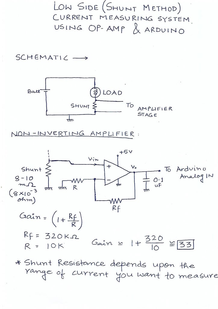
Ways to measure current: 1- Indirect method: such as current transformers (in the figure) and Hall effect sensors, which relies on Faraday's law of induction to sense current in a circuit and convert it to a proportional voltage. These methods are suitable more for high current systems. 2- Direct method: which relies on Ohm's law which states that V = I x R. fundamentals of current sensing circuits. It introduces current sensing resistors, current sensing techniques and describes three typical high-side current sensing implementations, with their advantages and disadvan-tages. The other current sensing implementations are beyond the scope of this application note and reserved
